Fault Finding - A Guide
Step by Step Guide
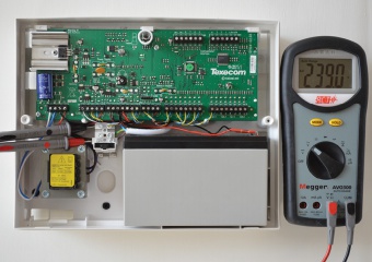
Step 1.1
MAINS VOLTAGE ACROSS LIVE AND NEUTRAL
- Switch multimeter to highest AC range
- Connect test probes across live and neutral
- Reading should be between 220 and 250VAC and reasonably stable
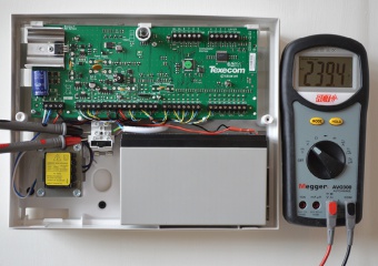
Step 1.2
MAINS VOLTAGE ACROSS LIVE AND EARTH
- Connect test probes across live and Earth
- Reading obtained should be almost identical to previous reading
- A difference of more than 1.2VAC means an Earth fault may exist
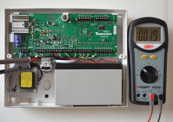
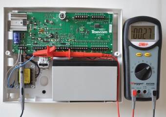
Step 1.3
MAINS VOLTAGE ACROSS NEUTRAL AND EARTH
- Switch the multimeter to 20VAC range
- Connect test probes across neutral and Earth
- Reading should not exceed 1.2VAC (example shows 0.019V)
Step 2
POWER SUPPLY CURRENT NORMAL (UNSET)
- Switch meter to highest AC current range
- Disconnect either AC output lead to panel
- Connect test probes in series with removed lead and power supply terminal
- Record AC mA reading obtained
Step 3
POWER SUPPLY CURRENT IN ALARM
- Generate a full alarm condition
- Record AC mA reading obtained
- Excessive current in this or previous test indicates a system fault
- Disconnect 12VDC supply to PIRs, bells, battery etc in turn to identify fault
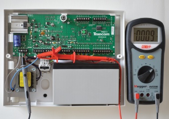
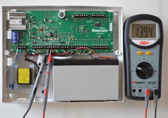
Step 4
INDUCED AC VOLTAGE
- Switch multimeter to 20VAC range
- Connect probes across any DC+ and Earth
- Induced AC reading should not exceed 1.2V
- To eliminate induced AC, fit an ACT 1313 12V spike suppressor
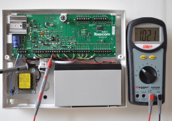
Step 5
BATTERY CHARGING VOLTAGE
- Switch multimeter to 20VDC range
- Connect test probes across battery
- Reading should be between 13.5 - 14VDC (Below 13V the battery will not charge, above 14.5V the battery will overcharge)
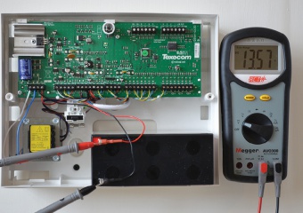
Step 6
AUXILIARY DC VOLTAGE
- Connect probes across auxiliary DC supply
- Reading obtained should be within 0.5VDC of battery charging voltage
- Any variation >±1VDC may cause false alarms

Step 7
BATTERY FLOAT CHARGE
- Switch multimeter to DC mA range
- Remove red charge lead from battery
- Connect test probes in series with removed charge lead & positive battery terminal
- A double mA reading, falling to a single mA reading should occur within 30 seconds
- If a constant high or no mA reading, replace battery
Step 8
BATTERY CURRENT NORMAL (UNSET)
- Switch multimeter to 20A DC range
- Disconnect mains supply by removing panel or 'spur' fuse
- Reading ideally should not exceed 5% of battery capacity (7Ah = 350mA)
Step 9
BATTERY CURRENT IN ALARM
- Generate a full alarm condition
- Reading ideally should not exceed 10% of battery capacity (7Ah = 700mA)
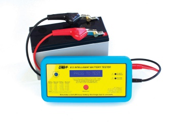
Step 10
BATTERY CAPACITY TEST
- Disconnect battery from control panel
- Check battery terminals are clean
- Connect battery tester leads red+ black-
- Record ambient temperature, DC voltage and Ah capacity available
- Replace battery when capacity falls below 65% (e.g. 7Ah replace below 4.55Ah)
Click here to download our Fault Finding guide as a .PDF